| W E L C O M E | Version 3.00C |
|
Adventures in Piconet |
||
"Piconet is an expansion network for Nimbus peripherals"
Not a great deal is known about the RM developed Piconet system, the story goes it was the brainchild of Mike Fisher.
It was essentially a serial based network for devices that acted ether as a Serial or Parallel port.
Piconet modules could be daisy chained off each other, upto the limit of 30 modules.
I understand different modules were planned, but from what I can gather never produced.
The Piconet system was built on existing technology provided by Intel, via the 8051 and 8031 8-bit microprocessor.
It utilised the interprocessor communication channel to speak with the various modules.
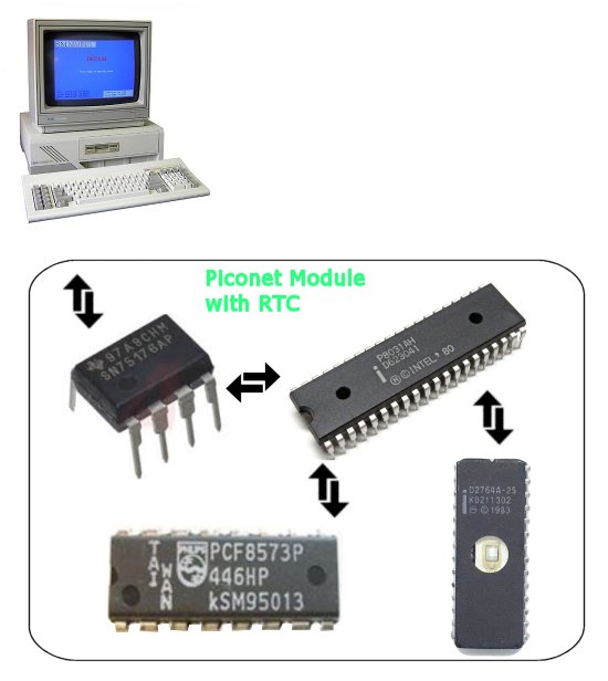
The modules would contain an Intel 8031 with a D2764A ROM, linked by 2 wires via an SN75176AP RS-485 Bus Transceiver to the Nimbus PC.
This allowed large distances to be covered between the Nimbus and modules, the manual stating upto 3 meters, however
it should be possible for much larger distances.
The serial protocol used was 1 Start Bit, 8 data bits, 1 control/address bit and 1 stop bit.
My testing suggests its runs at 333,600 Baud

The specific commands used in the process is proptietary to RM and although I have successfully decoded the proccess used for the RTC on the original internal Piconet serial card the rest is so far undecoded.
I understand that a document detailing the system was produced in 1985 by Mike Maloney, titled:
"Nimbus Piconet interface specification", however I have so far been unable to locate Mike or the document.
In my experiments with Piconet I wanted to decode the internal communication between the Real Time Clock that was originally fitted to the Piconet Serial card and the Nimbus. If I could get this decoded I could re-engineer a dedicated Piconet module that simply acted as an RTC for the Nimbus.
You see the Nimbus was hard coded to look for a serial Piconet module at address number 1 for a clock source on bootup in DOS.
If one was fitted the time and date would be automatically set. Equally setting the time in DOS would automatically update the RTC, all seemlessly unknown to the user. The problem being that the serial Piconet card is a very rare thing and the batteries generally have corroded and damaged the board.
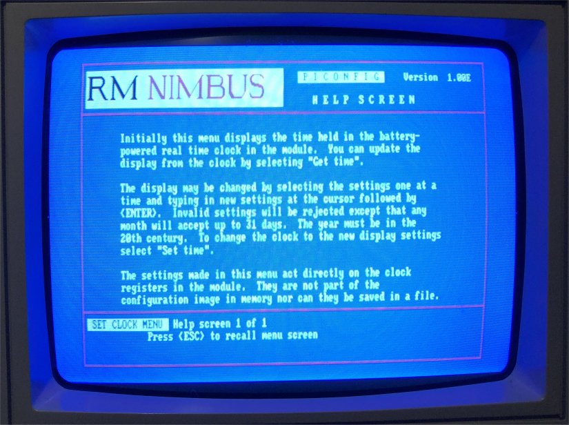
Interestingly the help screen suggests that the original serial RTC was not Y2K compliant, however my testing didn't seem to suggest this.
My testing showed that the process expects a 2 digit year, therefore is reliant on DOS3.3 interpreting those 2 digits correctly, testing showed that a date of 79 was turned into 2079, however 80 was reverted to 1980. So the Nimbus can keep time until 2079!
What I wanted was a seperate RTC only module that worked via the Piconet network and simply plugged into the back of the Nimbus, no configuration required.
What follows is my investigation into this, which successfully replicated the RTC system in an Arduino Nano.
The following shows the components we are interested in when trying to duplicate the RTC functionality:
As said, the protocol from the Intel 8031 to the RS-486 transceiver is TTL serial.
Viewing a communication on the scope looks like this:
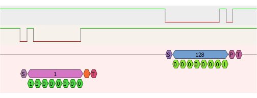
Here we can see that the Nimbus is asking if there is a module on address number 1.
There is and it replies with 128, essentially its just saying hello, I'm here.
The request has the 9th bit set to 1 to indicate that it is addressing a module with the address in the 8 data bits.
This means that all other modules can ignore it if they are not on address 1.
The intel 8051/31 has inbuilt UART functionality to work with this addressing system.
However in my testing I discovered that more indepth communications with modules were started with a higher number, module 1, for example, would be addressed with address 65, module 2 with 66 etc.
The Piconet config application, 'PICONFIG' has a screen which queries each of the possible 30 Piconet modules and displays their information on the screen
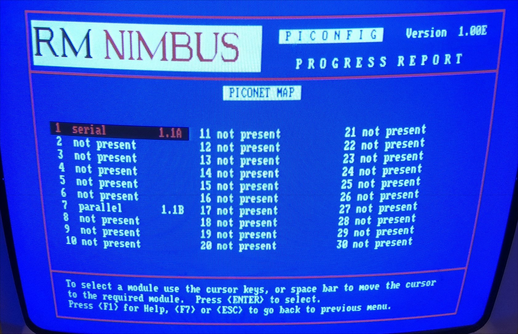
In my testing I found that the only 2 possible options that could be displayed on this screen was serial and parallel devices.
The module doesn't spell out its name, it does however give its version number and if its a serial or parallel device.
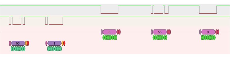
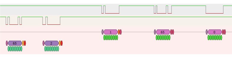
For example the following shows the data flow during a query by the Nimbus to a serial module:
From Nimbus |
Reply from module |
Usage? |
65(9th bit set),1 |
0,65,0 |
Module 1 are you there? |
65(9th bit set),2 |
1,65,0 |
Its asking here if module 65, which is address 1 is a serial or parallel device. 1=Serial |
65(9th bit set),25 |
65,65,0 |
Here it wants to know the version number, 65=A, 66=B etc |
65(9th bit set),24 |
1,65,0 |
Major part of the version number |
65(9th bit set),23 |
1,65,0 |
Minor Part of the version number |
Again on the scope this looks like:
Ignore the colour scheme for the 9th bit, my scope is treating it as a parity bit, not an address bit
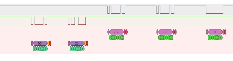
I found that the version 'number' can actually move into the alphabet characters simply by using a higher number reply, based upon the ASCII chart
So, based upon these investigations I was able to discover what the Nimbus does to request the time/date and what it returns to set the time/date.
I translated these findings into Arduino C code and used an Arduino Nano, DS3231 RTC, SN75176AP RS-485 IC and produced a standalone RTC Piconet module.
It is restricted to pretending to be a full serial module that the Nimbus was desiged for, so of course should you delve into the piconfig menu its going to get confused that its not getting the response it was intended to get. However it works as intended simply as a Real Time Clock.
The Nimbus boots up, automatically finds and queries the module and sets the DOS time/date accordingly. Equally should you change the date/time in DOS that gets sent to the Ardino also.
Its hard coded to Address 1, as that is where the Nimbus expects to find an RTC
MORE TO FOLLOW...
 |
Main Menu |